Pooky Control-Flow Flattening - Part 1
Nightmares from Pooky Switch Statements
One of the scariest things that I noticed as soon as I opened Pooky and beautified it via Sublime, was the excessive amounts of For Loops with an inner Switch Statement as the only element in the body.

Just looking at those Switch Cases for the first time gave me goosebumps. Trying to follow the logic on the flow will drive you nuts, as you usually have to make a mental note of what's comes next after every break statement.
I remember telling myself
There was no way in hell I was going to follow every single Switch Case logic by hand, or in my head.
So then I began to study them closely, figuring out the pattern, what they were made off, and how to make them SIMPLER. I knew deep down in my heart that these Switch Statements might look frightening but turning them into a much easier form to read would make my life easier with deobfuscating Pooky.
Nothing More Than Directed Acrylic Graphs
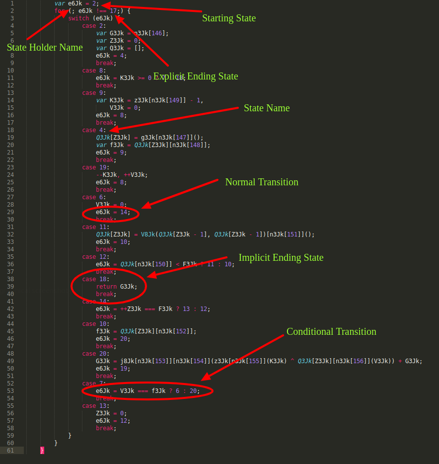
Within an hour I found out that these butt ugly Switch Statements were nothing more than Directed Acrylic Graphs(DAGs) in disguise. Each DAG had the same 4 major components:
- A State Holder Name
- An explicit Starting and Ending State, and sometimes an implicit Ending State was also included
- A list of States each from a Switch Statement Case that each had 0,1 or 2 transitions.
- A For Loop that advances to the next state in the DAG
States
Each Switch Case was a State in the DAG. The Switch Case test property was the State's name.
case 2:
    var G3Jk = n3Jk[146];
    var Z3Jk = 0;
    var Q3Jk = [];
    e6Jk = 4;
    break;
Every single State had either 1 and 2 transitions or 0 transitions if they were an Ending State.
Besides the states that had 0 transitions, each State contained what I would like to call a Conditional Transition or a Simple Transition.
A Conditional Transition is a transition that is based on the result of a predicate.
e6Jk = V3Jk === f3Jk ? 6 : 20
A true result would lead to one state, and a false state would lead to the state.
SimpleTransition is a transition that had only 1 transition that was not based on a predicate's result. This was really wasy to follow, as it never had any branches to follow.
Eventually, it was quite obvious to see that these Cases were nothing more than glorious Go-To statements that created the same logic as a If Then, If Then Else, and/or While Loop structures.
The body of the Switch Case was all the nodes that were inside the consequent property minus the following nodes:
- BreakStatement - which was always the last node in the
consequentproperty from each Switch Case. I always discarded this node as it was only needed for the Switch Case to operate as needed. - ReturnStatement - whenever this was found inside the
consequentproperty it meant that this State was going to be an `Ending State. I then proceeded to mark this state as an additional Ending State in my deobfuscator. - State Holder Name - Right before each BreakStatement the next state was set at the State Holder Variable . In the case of a State containing a Conditional Transition, the predicate's result was the value of the next state depending on the
trueorfalsevalue.
State Holder Name
The State Holder Name was nothing than a fancy name I gave it to the variable name that held the state of each DAG.
var e6Jk = 2;
It was always right above the Switch Statement so it was relatively easy to find, and it always came in the form of a Variable Declaration.
This State Holder Name or should we say variable was always redefined at the end of each Switch Case. Well, it was right before the last element which was always a Break Statement.
Starting State
The State Holder Name always had a Starting State. This was the State that the DAG always started in. Every DAG started with this first State, and it was always initialized with the Variable Declaration that initialized the State Holder Variable.
Ending State
As all DAG must eventually have all edges(transitions in our case) lead to some sort of ending state, an explicit Ending State is always set inside the For Loop test property.
for (; e6Jk !== 17;) //An Explicit Ending State

case 18:
    return G3Jk; // An Implicit Ending State
    break;
There was also another type of Ending State, one I like to call an implicit Ending State. This state was always defined when a State had a Return Statement, making this State an Ending State because it had 0 transitions.
For Loop
The For Loop acted as the loop that went to the next state as long as the final state hasn't been reached. This For Loop had some interesting properties that made it super easy to identify.
First, the init and the update properties were always set to null. Facilating with ease traversing the Javascript AST for any For Loops that had both of these properties set to null was one way that I used to identify each DAG.
The test property always had a Binary Expression with the operator property set to !==.
The left property was the State Holder Name,and the right property current state was not an Ending State, and will constantly loop until a Return Statement(an implicit Ending State) was found from each Switch Case or the explicit Ending State was found.
Note: Even though there was always an explicit Ending State set inside the For Loop
testproperty, the reality was that almost always(with a few exceptions) the explicit Ending State was never reached or even existed, to begin with. The implicit Ending State, the State that had a Return Statement, was always the case of how the DAG reached its Ending State.
Conclusion
More or less, this is a simple gist of what these Switch Cases were supposed to be. In the next part I will explain what sort of structures you would end up getting from these Switch Cases once they were fully simplified to a much friendlier form. Then, the following parts will go more into detail about the tools and algorithms I used to accomplish my goal of simplyfying these Switch Cases.