Pooky Control-Flow Flattening - Part 3
For Part 3 of this series, I'm going to pick up from where I left off. This means I will be going into detail over what the State, Ending State, Starting State, and Transitions are.
Note: Read Part 1 and Part 2 to get solid foundation that will help you understand Part 3 better.
However, this post is very important in itself as it will go over some concepts that will be fully explained in the later posts of this series.
Some of these concepts will take a whole post to completely describe how they play an integral part in simplifying Switch Cases to a more readable form.
A Deep Dive into States
As I mentioned in Part 1 a huge part of understanding what these Switch Cases ultimately represent is based on the fact that they are DAGs(Directed Acyclic Graph).
The nodes are represented as States and the edges as Transitions. There must be at least 1 Starting State and 1 Ending State, and you can never loop back to the Starting State from the Ending State.
Each of these States has a 1 or 2 transition(s) unless of course, they are an Ending State which they have 0 Transitions.
Going Back To Part 1
Let's look back at our SwitchStatement example from Part 1 to better illustrate the idea behind States and Transitions.
function notimportant(){
    var e6Jk = 2;
    for (; e6Jk !== 17;) {
        switch (e6Jk) {
            case 2:
                var G3Jk = n3Jk[146];
                var Z3Jk = 0;
                var Q3Jk = [];
                e6Jk = 4;
                break;
            case 8:
                e6Jk = K3Jk >= 0 ? 7 : 18;
                break;
            case 9:
                var K3Jk = z3Jk[n3Jk[149]] - 1,
                    V3Jk = 0;
                e6Jk = 8;
                break;
            case 4:
                Q3Jk[Z3Jk] = g3Jk[n3Jk[147]]();
                var f3Jk = Q3Jk[Z3Jk][n3Jk[148]];
                e6Jk = 9;
                break;
            case 19:
                --K3Jk, ++V3Jk;
                e6Jk = 8;
                break;
            case 6:
                V3Jk = 0;
                e6Jk = 14;
                break;
            case 11:
                Q3Jk[Z3Jk] = V8Jk(Q3Jk[Z3Jk - 1], Q3Jk[Z3Jk - 1])[n3Jk[151]]();
                e6Jk = 10;
                break;
            case 12:
                e6Jk = Q3Jk[n3Jk[150]] < F3Jk ? 11 : 10;
                break;
            case 18:
                return G3Jk;
                break;
            case 14:
                e6Jk = ++Z3Jk === F3Jk ? 13 : 12;
                break;
            case 10:
                f3Jk = Q3Jk[Z3Jk][n3Jk[152]];
                e6Jk = 20;
                break;
            case 20:
                G3Jk = j8Jk[n3Jk[153]][n3Jk[154]](z3Jk[n3Jk[155]](K3Jk) ^ Q3Jk[Z3Jk][n3Jk[156]](V3Jk)) + G3Jk;
                e6Jk = 19;
                break;
            case 7:
                e6Jk = V3Jk === f3Jk ? 6 : 20;
                break;
            case 13:
                Z3Jk = 0;
                e6Jk = 12;
                break;
        }
    }
}
Nothing But Headaches
At first glance, it's really hard to follow what's going on, it will require a lot of mental work just to keep track of what code gets executed.
The first line of code that gets executed as soon as you execute notimportant() is setting up your State Holder Variable to 2, which is our Starting State.
var e6Jk = 2;
After that, we enter our ForLoop.
for (; e6Jk !== 17;)
Note: Do you notice how the first thing in our
ForLoopcompares our State Holder Variable to another State? Yeah, this is the explicit Ending State ourForLoopwill exit once the State Holder Variable is set to this State.
Inside The SwitchStatement
Once inside the SwitchStatement all the nodes(lines of code) are executed.
Notice that each Switch Case will always have 2 nodes that are needed for this control-flow structure to work. These nodes are the last 2 nodes of each Switch Case. So, each Switch Case will always have at least 2 nodes inside its body.
The Semifinal Node
The semifinal node is a node that sets the next transition, the next state in our DAG(Directed Acrylic Graph).
Depending if the State is a normal state or a starting state then we will always encounter a Simple Transition or a Conditional Transition.
A Simple Transition looks like this:

And a Conditional Transition looks like this:

The main difference between a Simple Transition and a Conditional Transition is that the Conditional Transition will always be set in a If-Then-Else fashion. They are easy to identify because if the Semifinal node is a ConditionalExpression then the Transition found is a Conditional Transition .
For an explicit Ending State, the same pattern applies as the rest of all the other nodes. But when we are dealing with an implicit Ending State like in case 8 from our sample SwitchStatement.

Our DAG ends abruptly, and no new transitions will be followed.
The Last Node
The last node in our Switch Case which always be BreakStatement node on each Switch Case.
If our DAG ended abruptly because it reached an implicit Ending State, then the last node never gets executed.
On an explicit Ending State, it will still break out of the SwitchStatement returning to the beginning of the ForLoop.
Then the test property from the ForLoop will not execute anything inside the loop because the expression will evaluate to false. Making this the final state in the DAG, and ending the execution of all Switch Cases.
I've already established that the only possible explicit Ending State is the one found inside the test property of the ForLoopStatement. Thus, there can only be 1 explicit Ending State in our DAG.
The implicit Ending State is always going to be a Switch Case that has a ReturnStatement inside its body.
In most cases, only 1 implicit Ending State is found, but there are cases where multiple implicit Ending States are found inside our DAG.
Visualizing The Flow
A visual representation will make it easier to understand how each State flows into the next State.
As you can see in the graph below the flow of the Switch Cases gets very complicated to follow if you do it all in your head. And that's the intended purpose JScrambler had when it created them.

Everything seems pretty easy to follow until you get to State 8, from there things start to unravel and get harder to follow the flow.
Finding The Key Structures
Ultimately the States in the DAG can be represented into structures such as:
- If-Then
- If-Then-Else
- While Loops
- Do While Loops
On the colored flow diagram below from the same Switch Case, I've circled some of the key structures that are hidden behind all the Switch Cases found inside the Pooky files.

If-Then
The If-Then structures are circled in Yellow. They represent structures where either the true branch or false branch will converge at some point to the other branch.
Truth be told, once I was able to deobfuscate all the Switch Cases inside Pooky, I found out that these If-then structures were all littered around the codebase. The ugly truth is that most of these IfStatements were simply Opaque Predicates.
Some examples of what I'm talking about.
if (0) {
    g3Tk = g3Tk | 0x1ffff;
}
if (1) {
  f5Tk ^= K5Tk;
}
The first example is a useless node that will never be reached because it will always evaluate to false.
The second example is an IfStatement that never needed an IfStatement. You can simply extract the consequent body and replace the whole IfStatement with just the body nodes.
Without going further off tangent, I will move on to the other structures I saw while deobfuscating these Switch Cases. The later posts in this series I will go more into detail about some optimizations techniques I did to clean these Switch Cases a little bit more thoroughly.
If-Then-Else
While the If-Then structures were fairly useless most of the time, the If-Then-Else were not useless at all.
In the diagram above the one If-Then-Else structure is circled inPurple. The true and false branches all converged to a common State. Nothing too else to say about them.
While Loops
The While Loop is circled in Orange. One interesting aspect about these While Loops is that many of them didn't have that many break statements inside of them.
They were While Loops that had one branch(either the true or false) go inside the While Loop body while the other branch was always the next State.
That means that one branch never converged with the other branch because it required looping back to the main While Loop state to get out of the loop.
Do While Loops
Frankly, I'm still kind of mad that I spent a lot of time thinking about exotic structures that might appear in the 1750'ish SwitchStatements that I was trying to deobfuscate.
Note : The Do While Loops are exceedingly rare in Pooky. Only 3 exists and > they all play an important role in the evals. If you don't know what evals are, don't worry because I will talk more about them in another blog post series I have planned.
Let's use another Switch Case example that contains a Do While Loop
function notsoimportant(j9sk, l9sk, a9sk) {
    var Z9sk = 2;
    for (; Z9sk !== 32;) {
        switch (Z9sk) {
            case 22:
                u9sk = L9sk + (h9sk - L9sk + l9sk * P9sk) % R9sk;
                p9sk[P9sk][u9sk] = p9sk[h9sk];
                Z9sk = 35;
                break;
            case 35:
                h9sk -= 1;
                Z9sk = 18;
                break;
            case 6:
                var u9sk;
                Z9sk = 14;
                break;
            case 33:
                return p9sk;
                break;
            case 11:
                t9sk += 1;
                Z9sk = 13;
                break;
            case 27:
                L9sk = v9sk;
                v9sk = a9sk[w9sk];
                R9sk = v9sk - L9sk;
                w9sk++;
                Z9sk = 23;
                break;
            case 13:
                Z9sk = t9sk < j9sk ? 12 : 10;
                break;
            case 20:
                Z9sk = P9sk < j9sk ? 19 : 33;
                break;
            case 17:
                w9sk = 0;
                v9sk = 0;
                Z9sk = 15;
                break;
            case 15:
                L9sk = v9sk;
                Z9sk = 27;
                break;
            case 19:
                h9sk = j9sk - 1;
                Z9sk = 18;
                break;
            case 9:
                var v9sk;
                var L9sk;
                var R9sk;
                Z9sk = 6;
                break;
            case 10:
                P9sk = 0;
                Z9sk = 20;
                break;
            case 23:
                Z9sk = h9sk >= v9sk ? 27 : 22;
                break;
            case 18:
                Z9sk = h9sk >= 0 ? 17 : 34;
                break;
            case 12:
                p9sk[t9sk] = [];
                Z9sk = 11;
                break;
            case 14:
                t9sk = 0;
                Z9sk = 13;
                break;
            case 34:
                P9sk += 1;
                Z9sk = 20;
                break;
            case 2:
                var p9sk = [];
                var t9sk;
                var P9sk;
                var h9sk;
                var w9sk;
                Z9sk = 9;
                break;
        }
    }
}

And right here we have the flow chart:
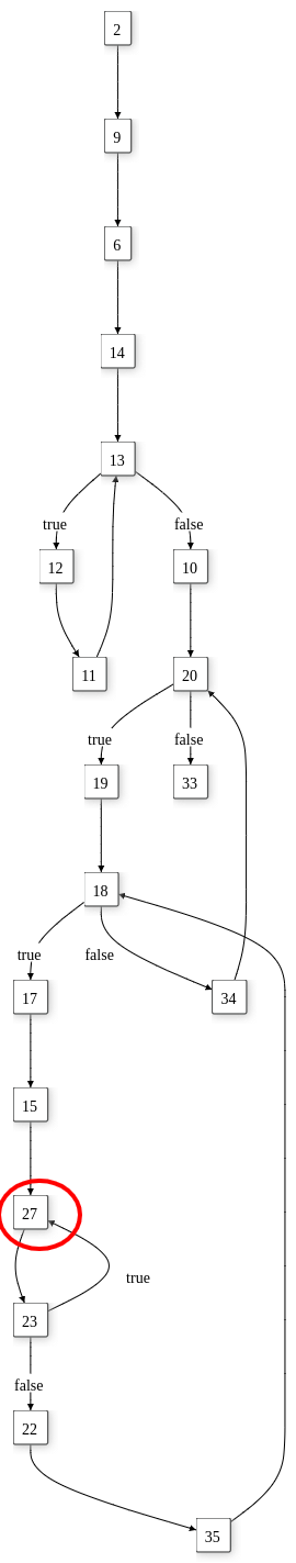
The Do While Loop circled in Red had a few interesting properties:
- They were all loopback States
- The main Do While Loop State always contained a Simple Transition, unlike its cousin, the While Loop State contained a Conditional Transition.
Extra Things To Look For
Implicit Ending State
Although not really a unique structure, the implicit Ending State circled in Orange, tended to be right outside the While Loops.
In some cases, they were inside the While Loops, but it was more common to find them outside the loops.
End Of The While Loop
It was imperative that I recognized where the While Loops ended because the End of While Loops circled in Black was also a type of abrupt ending.
I spent a lot of time debugging the End Of While Loops because at the very beginning my code was extremely buggy. When I couldn't find the End Of The While Loop* Tons of Maximum call stack size exceeded errors crashed my deobfuscator which was based on recursive calls that followed the next State in the DAG.
The Final Form Of A Switch Case
The result after running my deobfuscator on these Switch Cases look like this for the first diagram:
function notimportant() {
    var G3Jk = n3Jk[146];
    var Z3Jk = 0;
    var Q3Jk = [];
    Q3Jk[Z3Jk] = g3Jk[n3Jk[147]]();
    var f3Jk = Q3Jk[Z3Jk][n3Jk[148]];
    var K3Jk = z3Jk[n3Jk[149]] - 1, V3Jk = 0;

    while (K3Jk >= 0) {
        if (V3Jk === f3Jk) {
            V3Jk = 0;

            if (++Z3Jk === F3Jk) {
                Z3Jk = 0;
            }

            if (Q3Jk[n3Jk[150]] < F3Jk) {
                Q3Jk[Z3Jk] = V8Jk(Q3Jk[Z3Jk - 1], Q3Jk[Z3Jk - 1])[n3Jk[151]]();
            }

            f3Jk = Q3Jk[Z3Jk][n3Jk[152]];
        }

        G3Jk = j8Jk[n3Jk[153]][n3Jk[154]](z3Jk[n3Jk[155]](K3Jk) ^ Q3Jk[Z3Jk][n3Jk[156]](V3Jk)) + G3Jk;
        --K3Jk, ++V3Jk;
    }

    return G3Jk;
}
For the second diagram, the one that contains the Do While Loop, the code looks like this:
function notsoimportant(j9sk, l9sk, a9sk) {
    var p9sk = [];
    var t9sk;
    var P9sk;
    var h9sk;
    var w9sk;
    var v9sk;
    var L9sk;
    var R9sk;
    var u9sk;
    t9sk = 0;

    while (t9sk < j9sk) {
        p9sk[t9sk] = [];
        t9sk += 1;
    }

    P9sk = 0;

    while (P9sk < j9sk) {
        h9sk = j9sk - 1;

        while (h9sk >= 0) {
            w9sk = 0;
            v9sk = 0;
            L9sk = v9sk;

            do {
                L9sk = v9sk;
                v9sk = a9sk[w9sk];
                R9sk = v9sk - L9sk;
                w9sk++;
            } while (h9sk >= v9sk);

            u9sk = L9sk + (h9sk - L9sk + l9sk * P9sk) % R9sk;
            p9sk[P9sk][u9sk] = p9sk[h9sk];
            h9sk -= 1;
        }

        P9sk += 1;
    }

    return p9sk;
}
Conclusion
Thanks for making it this far in the series. In the next post of this series, I will go ahead and introduce the techniques and algorithms I used to simplify these Swith Cases.
Next part I will continue where I left off on Part 2 and talk more about the Control Flow class and the inner parts of my deobfuscator.
Until then... see ya next time.